Saturday, September 25, 2010

Results of my second MEPT experiment

From 16/9/2010 to 24/9/2010 my 30m MEPT was transmitting on 10140.080 KHz with FSKCW6 and only 160mW of power. This time the results were much better compared to the first experiment.

I received reports from 14 stations (DL4MGM, G4CDY, G6AVK, I2NDT, ON5EX, ON5SL, OZ9QV, PA0TAB, PA1GSJ, VE1VDM, VK2DDI, W1BW, W4HBK, ZL2IK) that are located on 10 DXCC countries (Germany, England, Italy, Belgium, Denmark, Netherlands, Canada, Australia, United States, New Zealand) and 3 continents (Europe, North America, Oceania). My longest DX was ZL2IK from New Zealand (again) but this time through long path! The long path distance between us (from KM17uw to RF74ci) is 22628 km and this rises my personal QRPp record to 141425 Km Per Watt!

The experiment results have been compiled as a KML file that is readable from Google Earth and Google Maps. In this way the reception reports log is more interactive. The color of each placemark defines the type of the station (MEPT or receiver). When the user clicks on a placemark the description of the reception report appears (date, time, location etc) including a small thumbnail of the received signal that is linked with the full size screenshot of the FFT software. The final result of the produced KML file is shown below:


View Larger Map

Many thanks to all stations that sent me their reports. More experiments will come with lower power levels and slower code speeds. Stay tuned!

References:
[1] QRSS Knights, Mailing List, http://cnts.be/mailman/listinfo/knightsqrss_cnts.be
[2] Google, Google Maps, http://maps.google.com
[3] Google, Google Earth, http://earth.google.com
[4] SV8GXC, Results of my first MEPT experiment, http://sv8gxc.blogspot.com/2010/09/results-of-my-first-mept-experiment.html

Sunday, September 19, 2010

My MEPT to ZL land through short and long path

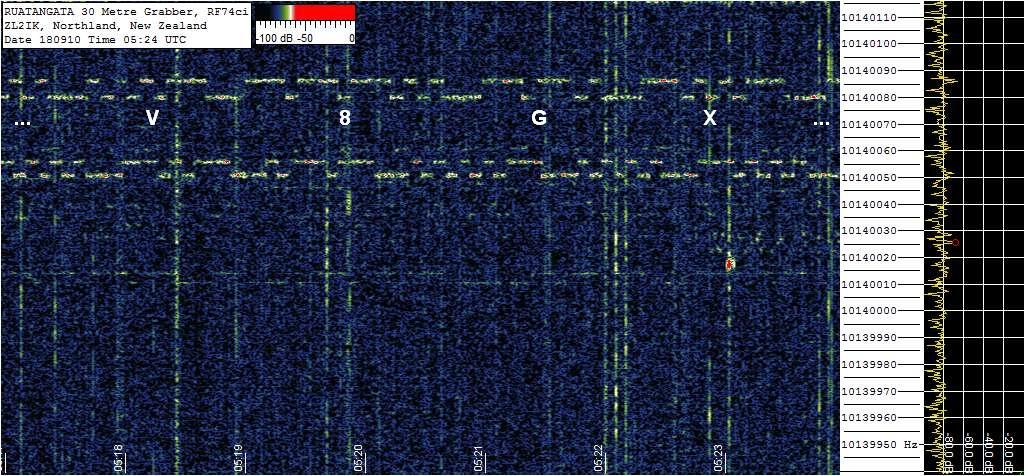
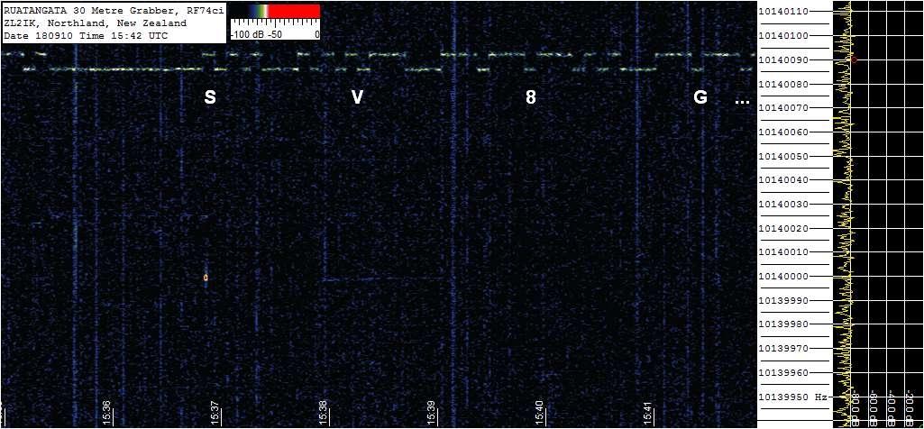
Today was very special for my tests. This morning Peter ZL2IK from Northland, New Zealand, sent me a reception report through the QRSS Knights Mailing List and he was writing the following:

“Hi Knights and George

Within the last 24 hours I have received George SV8GXC on the Long Path, via the Atlantic and Pacific Oceans, and on the Short Path via the Middle East/Indian Ocean/and Australia. See attached grabs, taken overnight my time…”


Long path from SV to ZL


Short path from SV to ZL

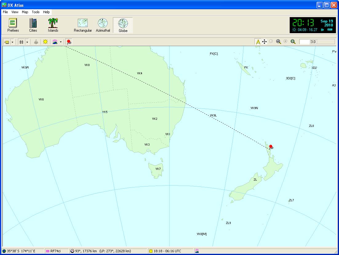
With the help of DX Atlas software (by Alex VE3NEA), I was able to calculate the actual distance between my grid locator (KM17uw) and Peter’s ZL2IK grid locator (RF74ci). The distances for short and long paths are 17376km and 22628km. Based on the facts that my MEPT’s transmitting power is only 160mW and that ZL2IK is my longest DX, Peter’s new long path reception increased my personal KPW (Km Per Watt) score from 108600 KPW to 141425 KPW. Thanks Peter!


SP and LP distances on DX Atlas

References:
[1] SV8GXC, My 30m QRPp MEPT, http://sv8gxc.blogspot.com/2010/09/my-30m-qrpp-mept.html
[2] QRSS Knights, Mailing List, http://cnts.be/mailman/listinfo/knightsqrss_cnts.be
[3] VE3NEA, DX Atlas Software, http://www.dxatlas.com/DxAtlas

Saturday, September 18, 2010

Improvements on my 30m MEPT

On 14/9/2010 I changed the transmission mode from FSKCW3 to FSKCW6 (by reprogramming the keyer microcontroller) and went back on the air on same frequency. The 3 dB improvement on SNR (because of mode change) didn't seem to be enough to make my signal detectable on US grabbers (at least during daytime where I am not sleeping and I am able to check the websites). So next day (15/9/2010), after a lot of trials and errors, I succeed to remain within the 100Hz QRSS window and stay stable on 10140.075 after the MEPT's warm-up period. After my comment on QRSS Knights mailing list for the reason of my frequency change, I received the same day, an email from Bill W4HBK in Florida. Bill wrote me that he was receiving my signal "often" and it was "one of the strongest from Europe" BUT he forgot to send me the report through the mailing list. He commented that my signal was appearing every day around 3:30 UTC (during my sleep) when the local US signals fading out. He also sent some screenshots of my FSKCW6 signal and was asking more info about my antenna. Now, it was clear, that my FSKCW3 experiment was more successful than I thought. My signal was detected from USA grabbers but I was sleeping "too much"... to realize it!

The next days, I continued to transmit on a 24-hour basis because I wanted to check if I will receive better results with the FSKCW6 mode. From the first day, the MEPT was working without any special box for ground or thermal shielding. Even that this didn't seem to be a problem, after the frequency change (I did) to 10140.75, I realized (by checking the online grabbers) that every time I was sitting on my desk, my "body capacitance" was affecting the MEPT's unshielded crystal oscillator and the frequency was detuned several Hz according to the distance between my body and the oscillator. Also the last days' weather change had as result several degrees change in the room's temperature and of course changes on transmission frequency. These frequency changes made the situation worse than before my QSY from .030 to .075. Now my signal, most of the day, was somewhere around .060 and it was always mixed with European MEPTs!

The idea of continuing to operate without ground and thermal shielding was not good at all. I should do something as soon as possible otherwise it would be better to stop the experiments. Even that the usage of a crystal oven is the optimum solution in applications where thermal stability is very important, in my experiments this would require a lot of time for oven's design and construction and would give more complexity to the project (something I didn't want). So I decided to do something (on the "quick and dirty" basis) that will improve the frequency stability without being complex.


Above you see the improvements... is not something special but is effective and very far from "rocket science". I just installed the MEPT inside a metal box that is grounded and makes MEPT unaffected from "body capacitance" and nearby metal objects. The metal box is installed inside a Styrofoam box that isolates thermally the metal box from the room environment. When we say thermal "isolation", we mean thermal energy (heat) transfer through the Styrofoam material in a very slow rate. Do you wonder how this affects the thermal stability of the MEPT? Inside the MEPT's circuit there are 3 transistors & 2 voltage regulators that produce heat during transmission. Under normal conditions and when the circuit works in "open air", the produced heat is dissipated in room's environment very fast and the transistors' surface temperature is a little bit higher than room's temperature. When the MEPT works inside the Styrofoam box, the produced heat is trapped in the air (inside the metal box) and the Styrofoam material does not allow the heat to be dissipated fast in the room. The result is to have a temperature inside the metal box many degrees higher than the room and a very slow rate heat transfer from inside to outside (of the Styrofoam box). In practice the metal - Styrofoam box works like an oven and makes the internal temperature unaffected from the rapid and small range temperature changes inside the room.

The modifications took place on 16/9/2010. Since then the Styrofoam box is warm and the MEPT is almost "locked" on 10140.080. No more frequency drifts because of proximity or room temperature changes. Of course, if I turn on the air conditioner or move the MEPT outdoors, the Styrofoam box is not enough to keep stable the MEPT's temperature (because of the great external temperature changes). In this case, a real crystal oven is the only solution and it will be one of my future projects. BUT for indoor usage, Styrofoam can give good results without increase complexity!

Reference:
[1] SV8GXC, My 30m QRPp MEPT, http://sv8gxc.blogspot.com/2010/09/my-30m-qrpp-mept.html

Monday, September 13, 2010

Results of my first MEPT experiment

From 10/9/2010 to 12/9/2010 my 30m MEPT was transmitting on 10140.030 KHz with FSKCW3 and only 160mW of power. From the first day of operation, I started to receive repeated reports through the QRSS Knights mailing list with positive comments. Based on my QRPp power I can say that the final results exceeded my expectations.

I received reports from 12 stations (G3VYZ, G4CDY, G6AVK, I2NDT, IZ1KXQ, ON5EX, ON5SL, PA0TAB, PA1GSJ, VK2DDI, VK6JY, ZL2IK) that are located on 6 DXCC countries (England, Italy, Belgium, Netherlands, Australia, New Zealand) and 2 continents (Europe, Oceania). Until now my longest DX is ZL2IK from New Zealand. The distance between us (from KM17uw to RF74ci) is 17376 km and this rises my personal QRPp record to 108600 Km Per Watt!

In order to have a better visual representation of my experiment results, I created the log as a KML file that is readable from Google Earth and Google Maps. In this way the reception reports log is more interactive. The color of each placemark defines the type of the station (MEPT or receiver). When the user clicks on a placemark the description of the reception report appears (date, time, location etc) including a small thumbnail of the received signal that is linked with the full size screenshot of the FFT software. The final result of the produced KML file is shown below:


View Larger Map

What comes next? First of all I will reprogram tomorrow the microcontroller to increase the dot length from 3 to 6 seconds (FSKCW6) and see how this will affect the quality of my signal as according to theory this change must improve my SNR to about 3 dBs. Also I will try to change my transmit frequency to a more clear spot within the 100Hz window because I noticed that around 10140.030 KHz there was a lot of activity in US and this made my signal undetectable from the US online grabbers (because of local QRM). Stay tuned!

References:
[1] QRSS Knights, Mailing List, http://cnts.be/mailman/listinfo/knightsqrss_cnts.be
[2] Google, Google Maps, http://maps.google.com
[3] Google, Google Earth, http://earth.google.com

Wednesday, September 8, 2010

My 30m QRPp MEPT

After a long & detailed theoretical description of the subjects that rely on the QRSS – QRPp experimentation field of amateur radio, today I will present you my 30m QRPp MEPT. Although I have a long experience with QRP and QRPp experiments via 2-way QSOs, this is my first attempt to experiment with QRSS on QRPp levels via Manned Experimental Propagation Transmitters (MEPTs). My MEPT operates inside the QRSS window of the 30m HF band (10140.0 - 10140.1 KHz). The circuit consists of two units: the transmitter and the keyer. The transmitter is based on two bipolar NPN transistors that the first works as a Colpitts oscillator and the second as a buffer and one N-Channel FET that works as a low power amplifier. The transmitter circuit is 80% identical to the 30m QRSS Kit designed by G0XAR & G0UPL. The transmitter's amplified signal is filtered with a 7 element Chebyshev low pass filter based on the short guide to harmonic filters of G3RJV. The bias of the N-Channel FET has been calibrated to produce an output of 8Vp-p @ 50Ohms that is equal to 160mW.


The keyer unit is based on the AT90S2343 AVR RISC microcontroller produced by Atmel. The microcontroller is configured to run with the internal RC 1MHz oscillator and is programmed with the appropriate firmware (written in BASCOM-AVR from MCS Electronics) to produce a repeated slow morse cw message with my callsign "SV8GXC". The dot length was programmed to 3 seconds. The cw-key output of the microcontroller drives a reverse polarized red LED that works as varicap and shifts the oscillator frequency to about 8Hz. The final result is an FSKCW3 signal at 160mW.

The above MEPT was tested in lab and soon will be on the air for experiments in collaboration with the QRSS Knights group. It will be tested for some days on FSKCW3 and the results will be presented in the next post. Stay tuned!

References:
[1] G0UPL, 30m QRSS Kit, http://www.hanssummers.com/qrsskit.html
[2] G3RJV, A short guide to harmonic filters for
QRP transmitter output, http://www.gqrp.com/harmonic_filters.pdf
[3] Atmel, AT90S2343 Datasheet, http://www.atmel.com/dyn/resources/prod_documents/doc1004.pdf
[4] MCS Electronics, BASCOM-AVR, http://www.mcselec.com/index.php?option=com_content&task=view&id=14&Itemid=41

Tuesday, September 7, 2010

MEPTs & QRSS Knights

In the previous posts we were described issues related to slow Morse code transmission, bandwidth (BW), signal to noise ratio (SNR) and operating modes such us QRSS and its variants. Today we will make one small step forward and we will see how these modes are used inside amateur radio for experimentation and propagation research. In future postings and within 3rd party references for experimentation with slow code transmission, you must keep in mind that the term "QRSS" is used in general.

MEPTs

For ionospheric propagation experiments the most common practice is the usage of radio beacons. Radio beacons are unattended transmitters that repeat a callsign in Morse code (most of the times) and the listeners by identifying each beacon can know if the specific moment of reception there is a propagation opening between their location and the location-country of the beacon. In many countries the amateur radio license forbids the licensee to operate a beacon without first obtaining special permission and/or an extension to the license. In some countries the licensing conditions relating to beacon operation are confusing. With QRSS operating it is quite common for low power transmitters to work for extended periods of time therefore it was felt among QRSS experimenters that is important to clarify their position with respect to beacons.


Since the QRSS experiments are directed at achieving the detection of very weak radio signals at great distances and examining how the prevailing propagation conditions affect those signals it was decided that a new term should be found to describe any QRPp slow code transmitting equipment which best suited these activities. After several threads on mailing lists related to QRSS experimentation over many months, the term "MEPT" was arrived that stands for Manned Experimental Propagation Transmitter. The "Manned" part of the term MEPT is simply to make clear that these transmitters are supervised at all times. The "Experimental" means just that, an experimental transmitter while the "Propagation" part of the term attempts to make it clear that QRSS transmitters are a method of observing propagation effects on radio signals. Above all QRSS experimenters try to avoid the term "beacon" because this can be a "sensitive" issue.

QRSS Knights

QRSS Knights is a worldwide known group of QRSS enthusiasts, that are doing experiments mostly on 30m (10140.0 - 10140.1 KHz) & 40m (7000.8 - 7000.9 KHz) and sometimes on 80m (3500.8 - 3500.9 KHz). I am not sure when they started to exist as group but I learned about them back in 2002. All of the experiments are done on QRSS, FSKCW, DFCW and some other slow code transmission modes like HELL. The maximum working power is below 500mW. Most of the times the power is 100 to 200 mW and there are cases were the experimentation goes down to the microwatts region. The QRSS Knights group consists from radio amateurs that work MEPTs or QRSS Grabbers and they exchange information and reception reports through the knightsqrss mailing list or the knightsqrss clipboard. As you may already understood… I am one of the QRSS Knights.


References:
[1] M0AYF, The term "M.E.P.T." explained, http://www.qrss.thersgb.net/MEPT.html
[2] QRSS Knights, Mailing List, http://cnts.be/mailman/listinfo/knightsqrss_cnts.be
[3] QRSS Knights, Clipboard, http://www.on5ex.be

Monday, September 6, 2010

QRSS, FSKCW & DFCW modes

In the previous post we described how effective is the reduction of the Morse code speed on the SNR and how much we can reduce our transmitting power if we reduce our code speed. Most of you may think: "Why we need to lower the code speed to extreme numbers (like many seconds per dot) since we can use some Watts and communicate in normal speeds?" Even that this question can be answered on many different ways, there are some cases where the transmission on extremely low speeds is the only option. One of them is the case were we need to transmit on ELF, SLF, ULF, VLF or LF bands where wavelength ranges from 100000km to 1km. In any of these bands the wavelength is so long that is impossible to construct a normal transmission antenna with length at least one quarter of the wavelength. In all cases the transmitting antenna will be very short compared to the wavelength and because of that its impedance will be many KOhms compared to the 50 Ohms of the transmitter output. In these cases we need special antenna tuners with huge tunable coils (variometers) that will match the impedance of our antenna with the impedance of the transmitter. The final result is a lot of power consumption on the antenna tuner and only a small part of the transmission power is radiated on the air (Effective Radiated Power or ERP). A typical example in amateur radio is the band of 136 KHz (LF) were we need at least 600 Watts of transmission power in order to produce only 1 Watt ERP! As we go lower in frequencies the radiated power becomes much lower and finally the ERP is the factor that defines what will be our Morse code transmission speed. Aside from the case that very low speed is mandatory, there are cases were radio amateurs experiment on high frequencies with very low code speeds just for the fun in order to play with QRPpp power levels and break MPW world records. There are several techniques (modes) for slow Morse code transmission. The most widely used from radio amateurs are QRSS, FSKCW and DFCW.

QRSS

QRSS is extreme slow speed CW, the name is derived from the Q-code QRS (reduce your speed). To take advantage of the very narrow bandwidth of the transmitted signal an appropriate filter at the receiver end is needed. Making a "software filter" using FFT (Fast Fourier transform) has some advantages over the old-fashioned hardware filters. One of the main advantages, when using it for reception of slow CW signals, is that FFT does not give you one single filter but you get a series of filters with which you can monitor a complete spectrum at once. This means that you do not have to tune exactly into the signal, something that can be very delicate at sub-Herz bandwidths. Also it is possible to monitor more than one QRSS signals at the same time. Further the long duration of the dots and dashes is unfavorable for aural monitoring. A solution to the above problem is to show the outcome of the FFT on screen rather than making it audible. The result is a graphic where one axis represents time, the other axis represents frequency and the color represents the signal strength. If the vertical axis represents time we call it a "waterfall" display while it is called a "curtain" display if the horizontal axis represents time. All this may sound complicated but it is easy to understand when you see the following example:


The picture above shows the signal of G3XDV as it was received on 15/01/05 from RU6LA on 136KHz with QRSS10 (10 second dots) on a two-way QSO that covered a distance of 2823km.

FSKCW

FSKCW means Frequency Shift Keying CW and is a variant of QRSS that instead of activate/deactivate the carrier, the carrier is always activated as long as the transmission lasts. During pauses between dots, dashes or characters the frequency is shifted downwards. Whilst the upper trace shown on the screen contains the morse information the lower trace is drawn during signal pauses. The advantage of this mode is its redundancy. If, for instance, a dash is falling into pieces caused by QRM there's still a chance to determine subsequently by checking the lower trace if the signal really had contained that dash or rather several dots.


The picture above shows the signal of WA5DJJ as it was received on 27/03/09 from WA0UWH on 10140KHz with FSKCW10 (10 second dots), the covered distance was 2176km.

DFCW

DFCW means Dual Frequency CW and is a combination of QRSS and FSKCW. In the LF band of 136KHz where the most common used mode is QRSS3, a very basic QSO will take about 30 minutes. Changing QRN levels and/or propagation during this period can have a vast effect on a QSO. Therefore the DFCW mode was developed that enhances the average speed by a factor of 2.5 to 3. In DFCW the element duration is replaced by the element frequency. So dots and dashes no longer have a different length but they are transmitted on a different frequency. Due to this frequency shift there is no space needed between the dots/dashes and the character space can be reduced to the same dot length. To make it even easier to read, especially during a sequence of dots or dashes, a short space (typically 1/3 of a dot length) is added between the dots and dashes. This reduces the average speed a bit, but is improves the readability and also reduces the transmission duty cycle. At a speed of 3 seconds per dot the CQ message will take 5'30" in QRSS while it will take only 1'54" in DFCW. The speed advantage of DFCW over QRSS can be taken in 2 ways, either by reducing the duration of a QSO or by increasing the dot length and working at a narrower bandwidth. The last means that, for the same duration of a QSO, the dot length in DFCW can be 2.5 to 3 times longer and as a result of this get a 4 to 5dB better SNR.


The picture above shows the signal of CT1DRP as it was received on 14/04/04 from OH1TN on 136KHz with DFCW120 (120 second dots), the covered distance was 3364km.

Reception of QRSS, FSKCW & DFCW

In order to receive signals of these modes you need of course an antenna and an SSB receiver for the frequency of interest. The audio output of the receiver must be connected to the soundcard of a PC and with the help of specialized software like: Argo, Spectran, SpectrumLab, QRSS VD and many others, you will able to receive and decode signals via the embedded FFT procedures.

References:
[1] Wikipedia, Radio spectrum, http://en.wikipedia.org/wiki/Radio_spectrum
[2] ON7YD, Extreme narrow bandwidth techniques, http://www.qsl.net/on7yd/136narro.htm
[3] DL6JAN, CWKtiny Instruction manual, http://www.proehl-elektronik.de/cwk/manual/manual5_e.html